Hioki LCR Meters and Impedance Analyzers range from 1mHz to 3GHz devices to suit a wide range of applications in the testing of electronic components. The IM3536 raises the industry standard for general-purpose LCR meters by offering a wide DC and 4Hz to 8MHz testing frequency while delivering 0.05% accuracy, ideal for evaluating the characteristics of next generation electronic components, including power supply inductors thanks to the instrument’s maximum measurement frequency of 8MHz.
Özellikler:
-
4 Hz ile 8 MHz arasında frekans ölçüm aralığı
-
LCR ve Sürekli Ölçüm Modları
-
Dielektrik Sabiti (ε ) ve iletkenlik (σ )ölçümü
-
Empedans ölçümünde ±0.05% temel doğruluk
-
1 ms ölçüm hızı
-
50 V a kadar DC Bias ölçümü
-
Harici ±40 V DC Bias Voltaj Destekleme Ünitesi
-
Harici 2A DC Bias Akım Destekleme Ünitesi
-
3 Yıl Garanti
-
Japon Malı
This product is not supplied with measurement probes or test fixtures. Please select and purchase the measurement probe or test fixture options appropriate for your application separately. All probes are constructed with a 1.5D-2V coaxial cable. For an RS-232C connection: A crossover cable for interconnection can be used. You can use the RS-232C CABLE 9637 without hardware flow control.
-
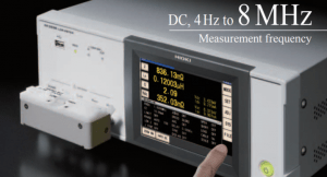
DC, 4Hz to 8MHz measurement frequency
-
High-speed measurement of 1ms (fastest time)
-
High-precision measurement of ±0.05% rdg. (representative value)
-
Guaranteed accuracy range from 1 mΩ, low-impedance measurement with unmatched repeatability
-
DC bias function: Measure under conditions simulating actual use or in accordance with industry standards
-
Exceptional specifications and cost-performance for a wide range of applications, from R&D to production lines
Measuring the Capacitance of Electrolytic Capacitors with Hioki LCR Meters
The measurement conditions under which the capacitance of electrolytic capacitors is defined are set forth by an IEC standard. However, since the capacitance of electrolytic capacitors varies significantly with the measurement frequency, capacitance values are also checked at the frequencies that correspond to the circuit conditions under which the components will actually be used. The LCR Meter IM3536’s measurement frequency can be set over a broad range of values (DC and 4 Hz to 8 MHz), making the instrument ideal for evaluating components under the conditions of actual use.
Measuring the Capacitance of Ceramic Capacitors with Hioki LCR Meters
There are two types of laminated ceramic capacitor: the high-dielectric type, whose capacitance varies with the measurement voltage, and the temperature-corrected type, whose capacitance does not vary. The measurement conditions under which capacitance is defined are set forth by separate IEC standards for the two types of component. The LCR Meter IM3536’s measurement frequency and measurement voltage can be set over a broad range of values (DC and 4 Hz to 8 MHz, and 10 mV to 5 V, respectively), making the instrument ideal for measuring laminated ceramic capacitors under a variety of conditions.
Measuring the Inductance of Inductors or Coils with HIOKI LCR Meters
The phenomenon of LC resonance based on the inductance of inductors (or coils) and the parasitic capacitance of coils is known as self-resonance, and the frequency at which self-resonance occurs is known as the self-resonant frequency. When evaluating a coil, measure L and Q at a frequency that is sufficiently lower than the self-resonant frequency. The LCR Meter IM3536’s measurement frequency can be set over a broad range of values (DC and 4 Hz to 8 MHz), making the instrument ideal for measuring and evaluating components while varying the frequency.
Measuring the Frequency Characteristics of Inductors on Hioki LCR Meters
The LCR Meter IM3536’s measurement frequency can be set over a broad range of values (DC and 4 Hz to 8 MHz), making it ideal for measuring and evaluating components while varying the frequency. You can install the included LCR sample application software (CD-R) on a computer and use it via the instrument’s interfaces (USB, GP-IB, or RS-232C) to vary the frequency at designated points and to save data obtained from automatic measurement as a Microsoft Excel or text file.
|
Teknik Özellikler |
|
Ölçüm Modları |
LCR Metre Modu Sürekli Ölçüm Modu |
|
Ölçüm Parametreleri |
Z, Y, θ, X, G, B, Q, Rdc (DC resistance), Rs (ESR), Rp, Ls, Lp, Cs, Cp, D (tanδ), σ, ε |
|
Ölçülebilir Aralık |
100 mΩ to 100 MΩ |
|
Görüntü Aralığı |
Z: 0.00 m to 9.99999 GΩ Y: 0.000 n to 9.99999 GS θ: ± (0.000° to 180.000°) Q: ± (0.00 to 9999.99) Rdc: ± (0.00 m to 9.99999 GΩ) D: ± (0.00000 to 9.99999) Δ%: ± (0.000 % to 999.999 %) |
|
Temel Doğruluk |
Z: ±0.65 % rdg. θ: ±0.38° |
|
Ölçüm Frekansı |
4 Hz to 8 MHz (100 kHz çözünürlük) |
|
Çıkış Empedansı |
Normal modda: 100 Ω, Düşük Empedans Yüksek Doğruluk modunda: 10 Ω |
|
Ekran |
5.7-inch renkli TFTdokunmatik ekran |
|
Ölçüm Hızı |
1 ms |
|
DC Bias Ölçümü |
DC Gerilim 0 V … 2.50 V (10 mV çözünürlük) Düşük Empedans Yüksek Doğruluk modunda; 0 V … 1 V (10 mV çözünürlük) |
|
Fonksiyonlar |
Kontak kontrolü, Karşılaştırıcı, BIN ölçümü, Panel yükleme/kaydetme, Hafıza Fonksiyonu, Açık/Kısa Kompanzasyonu, Korelazyon Kompanzasyonu |
|
Arayüzler |
EXT. I/O ,USB, USB flash drive, LAN, GP-IB, RS-232C, BCD |
|
Boyutlar ve Ağırlık |
330E×119Y×230B mm, 4.2 kg |
|
Standart Aksesuarlar |
Güç Kablosu ×1, Kullanım Kılavuzu ×1, LCR Uygulama CD’si ×1 |